Data modeling is the process of designing the structure, relationships, and attributes of a database or information system. It involves creating a conceptual representation of the data to ensure that it meets the requirements of the organization and supports efficient data storage, retrieval, and manipulation. One of the commonly used data modeling techniques is the Entity-Relationship (ER) model, which utilizes entity-relationship diagrams (ER diagrams). Here’s an introduction to data modeling concepts, with a focus on entity-relationship diagrams:
- Entities:
Entities represent real-world objects, concepts, or things that are relevant to the business or application being modeled. An entity is usually a noun, such as “Customer,” “Product,” or “Order.” Each entity has attributes that describe its characteristics or properties. For example, a “Customer” entity may have attributes like “CustomerID,” “Name,” and “Email.” - Relationships:
Relationships depict associations and interactions between entities. They describe how entities are connected or related to each other. Relationships can be one-to-one, one-to-many, or many-to-many. For instance, in a retail system, a “Customer” entity may have a one-to-many relationship with the “Order” entity, indicating that a customer can place multiple orders. - Attributes:
Attributes are the properties or characteristics of entities. They provide detailed information about entities. Attributes can be simple (e.g., “Name,” “DateOfBirth”) or composite (composed of multiple sub-attributes), and they can be either mandatory or optional. Attributes help define the structure and properties of entities within the data model. - Primary Keys:
A primary key is a unique identifier for each instance of an entity. It uniquely identifies a record in a table and ensures the integrity and uniqueness of data. Primary keys can be composed of one or more attributes that uniquely identify an entity instance. For example, a “CustomerID” attribute can serve as the primary key for the “Customer” entity. - Foreign Keys:
Foreign keys establish relationships between entities. They are attributes in one entity that refer to the primary key in another entity. Foreign keys maintain referential integrity, ensuring that the values in the relationship are consistent and valid. For instance, in an “Order” entity, a foreign key may reference the “CustomerID” from the “Customer” entity to associate an order with a specific customer. - Cardinality and Modality:
Cardinality defines the number of instances of an entity that can be associated with another entity through a relationship. It specifies the minimum and maximum number of occurrences. Modality refers to the required or optional nature of the relationship. Cardinality and modality help define the participation and constraints in a relationship, such as one-to-one, one-to-many, or mandatory relationships. - Entity-Relationship Diagrams (ER Diagrams):
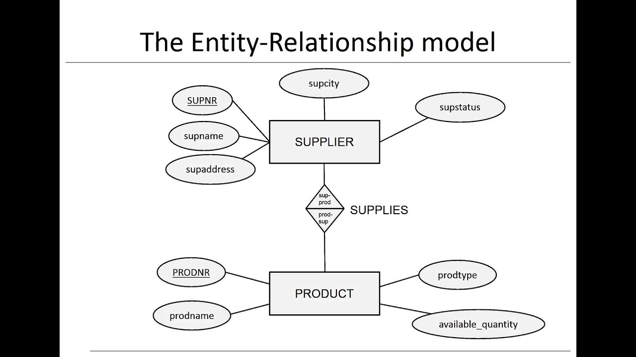
ER diagrams are visual representations of the entities, relationships, and attributes in a data model. They use boxes to represent entities, lines to represent relationships, and diamonds to represent attributes. Primary and foreign keys are indicated in the diagram, along with cardinality and modality notations. ER diagrams provide a clear and concise overview of the data model, aiding communication and understanding among stakeholders.
ER diagrams are a widely used technique for conceptual data modeling, allowing designers to represent the structure and relationships of data in a visual and intuitive manner. They serve as a foundation for database design, application development, and data integration processes.